The fundamentals of AMOLED technology, including pixel circuit design, driving methods, key manufacturing processes, structure, optimization, and technical advantages
1. Design and Optimization of Pixel Circuits
As the fundamental unit of a display panel, the performance of a pixel circuit directly impacts the image quality, energy consumption, and lifespan of the entire device. During the design process, the primary consideration is the circuit’s working principle, which generally involves charge storage, charge transfer, and emission control. Based on these fundamentals, designers must select appropriate transistor types, driving voltages, and current levels to ensure the pixel circuit operates stably under varying brightness and contrast conditions.

In the optimization phase, the focus shifts to enhancing response speed, lowering power consumption, and minimizing electromagnetic interference. This is typically achieved by adopting advanced CMOS process technologies, optimizing transistor layout and sizing, and introducing adaptive brightness control algorithms. Pixel circuit optimization is an ongoing process that must be integrated throughout the entire display system design, working in tandem with driving ICs and power management modules to achieve peak display performance and system efficiency.
2. Overview of Pixel Circuit Driving Methods
2.1 Basic Classification of Driving Methods
2.1.1 Theoretical Basis
In display technology, the driving method is a defining factor in display quality and performance. Each method has a unique theoretical foundation that dictates the design requirements and optimization directions of the driving circuit:
- Static Driving: The earliest driving method, it uses the switching characteristics of transistors to maintain pixel potential and usually requires no additional storage units. It is simple to implement and suitable for low-resolution displays.
- Dynamic Driving: Introduces storage capacitors to hold pixel potential, allowing pixels to remain illuminated longer. This supports higher resolutions and complex applications. It uses periodic refresh mechanisms to maintain image quality but increases circuit complexity.
- Grayscale Driving: An evolution of dynamic driving, it precisely controls pixel emission time or intensity to achieve distinct grayscale levels. This requires sophisticated driving strategies but delivers rich, highly detailed image performance.

2.1.2 Technical Requirements and Standards
The technical demands for driving methods revolve around key performance parameters. Different applications prioritize different metrics:
- Response Time: Rapid response is essential for fluid dynamic image display.
- Power Consumption: Minimizing energy use is critical, especially for portable devices.
- Stability: Circuits must remain stable over long-term use to prevent image retention (burn-in) or flickering.
- Lifespan: High-quality displays require durable pixel circuits to ensure product reliability.
Standardization is also a major driving force in display advancements. Organizations like the IEC and IEEE have established rigorous standards for testing and evaluating display performance, ensuring cross-manufacturer comparability and compatibility.

2.2 Optimization Strategies for Driving Methods
2.2.1 Circuit Design Optimization
Optimization strategies span circuit architecture, materials, and processes:
- Structural Optimization: Utilizing novel layouts like advanced TFT structures or charge-sharing techniques improves performance without inflating manufacturing costs.
- Material Selection: Deploying high-performance organic or inorganic semiconductor materials boosts stability and speed.
- Process Improvements: Advanced manufacturing techniques like laser annealing and Chemical Vapor Deposition (CVD) enhance precision and yield.
Example: Implementing charge-sharing logic in Verilog.
// Pseudocode: Charge Sharing Circuit Design
module charge_sharing_circuit(
    input clk,          // Clock signal
    input reset,        // Reset signal
    input [N-1:0] data_in,   // Input data
    output reg [N-1:0] data_out // Output data
);

// N is the data bit-width
parameter N = 8;

// Charge sharing logic implementation
always @(posedge clk or posedge reset) begin
    if (reset) begin
        data_out <= 0;
    end else begin
        // Implement charge sharing, assuming data_in represents signal lines between adjacent pixels.
        // Sharing is achieved by adjusting capacitor values and switch controls.
        // Specific logic depends on precise design details.
    end
end

endmodule
2.2.2 Power Management and Energy-Saving Technologies
Dynamic adjustment of voltage and current significantly reduces unnecessary energy loss:
- Dynamic Voltage and Frequency Scaling (DVFS): Adjusts power voltage and frequency in real-time based on display complexity.
- Local Dimming: Modulates backlight brightness for specific zones to enhance contrast while saving power.
- Circuit Sleep Technology: Puts circuits into a low-power sleep state in areas where pixel values do not need updating.
Example: Dynamic voltage adjustment in C.
// Pseudocode: Dynamic Voltage Adjustment Control Logic
void adjust_voltage(int demand) {
    float voltage = BASE_VOLTAGE;  // Base voltage value
    // Calculate adjustment based on display demand
    if (demand == HIGH) {
        voltage += voltage_adjustment_high;
    } else if (demand == MEDIUM) {
        voltage += voltage_adjustment_medium;
    } else {
        voltage += voltage_adjustment_low;
    }
    // Set power supply to the calculated voltage
    set_power_supply(voltage);
}

// Power supply adjustment function
void set_power_supply(float voltage) {
    // Hardware interface control code for voltage adjustment
    // ...
}
3. Differences and Applications of Static, Dynamic, and Grayscale Driving
3.1 Static Driving
- Working Principle: Maintains a constant pixel potential by holding a fixed voltage or current. Uses basic components: a switching transistor, a storage capacitor, and an LED.
- Advantages & Limitations: Highly cost-effective and simple to design, making it ideal for basic outdoor signage or low-resolution devices. However, it cannot support high refresh rates (unsuitable for video/gaming) and is prone to uneven pixel aging if displaying static images for too long.
3.2 Dynamic Driving
- Working Principle: Introduces time modulation to update pixel states rapidly. It achieves brightness levels through Pulse Width Modulation (PWM), controlling the duty cycle of pixel activation.
- Advantages & Limitations: Supports higher refresh rates and grayscale levels, perfect for HDTVs, monitors, and smartphones. The downside is increased power consumption due to high-frequency switching, accelerated component aging, and complex PWM algorithm requirements.
3.3 Grayscale Driving
- Working Principle: Builds upon dynamic driving by using voltage or current modulation to control emission intensity precisely, delivering nuanced grayscale tiers.
- Advantages & Limitations: Delivers hyper-realistic color depth and contrast for professional monitors, high-end TVs, and medical imaging. However, it requires highly complex data drivers and signal processing algorithms, increasing costs and demanding rigorous pixel lifespan management.

4. Overview and Advantages of AMOLED Technology
4.1 Basic Principles
4.1.1 Working Mechanism
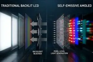
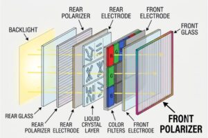
AMOLED (Active Matrix Organic Light-Emitting Diode) utilizes an active matrix to drive an organic light-emitting material. Unlike traditional LCDs that rely on a backlight, AMOLED is self-emissive. Every pixel is independently controlled by a thin-film transistor (TFT). When an electrical signal is received, the organic layer directly converts electrical energy into light.
4.1.2 Comparison with Traditional Displays
AMOLED outperforms TFT-LCDs in several ways: it boasts a near-zero response time (eliminating motion blur), offers infinitely better viewing angles, and enables ultra-thin form factors. However, challenges include higher manufacturing costs, overall lifespan concerns, and potential color shifting at extremely low brightness.
4.2 Application Advantages
4.2.1 Energy Consumption and Efficiency
Because AMOLED pixels turn off completely to display black, they consume zero energy in those areas. This makes AMOLED highly power-efficient for dark-mode interfaces and mixed-media viewing, cementing it as the premier choice for battery-dependent portable devices.
4.2.2 Viewing Angle and Color Performance
AMOLED provides purer blacks, brighter whites, and an expansive color gamut with high saturation.

4.2.3 Application Prospects
From cutting-edge smartphones and ultra-thin tablets to immersive VR headsets and next-gen automotive infotainment systems, AMOLED’s unique characteristics are driving a true display revolution.

5. Structural Composition and Working Principle of AMOLED
5.1 Basic Structure
A standard AMOLED panel consists of several critical layers working in unison:
- Glass/Flexible Substrate: The foundation requiring extreme flatness and chemical stability.
- TFT Array: The control matrix where each pixel is paired with a TFT switch for independent manipulation.
- Organic Emissive Layer: The core of the display, containing hole transport, electron transport, and emissive layers. When electrons and holes recombine here, they emit light (RGB).
- Cathode Layer: Usually a metallic material acting as the electron source.
- Encapsulation Layer: Crucial for protecting the organic materials from moisture and oxygen degradation.
5.2 Detailed Working Principle
5.2.1 Electroluminescence
When an electric field is applied, electrons are injected from the cathode and holes from the anode (TFT). They meet in the emissive layer, recombine to form an excited state, and release energy as photons (visible light) when returning to the ground state.
5.2.2 The Role of Driving Circuits
The driver IC manages TFT operation to ensure precise current delivery. Current control is paramount to uniform brightness and color, requiring sophisticated compensation algorithms for temperature fluctuations and organic material aging over time.

6. Key Technologies in the AMOLED Manufacturing Process
6.1 Manufacturing Process Flow
- Substrate Preparation: Rigorous cleaning of the base glass or polyimide substrate.
- Thin Film Deposition: Applying conductive, semiconductor, and insulating layers via PVD (Physical Vapor Deposition) or CVD.
- Photolithography and Etching: Transferring circuit patterns onto the substrate and etching away excess material.
- Active and Organic Layer Formation: Precisely depositing the delicate organic emissive layers (often via fine metal masks).
- Encapsulation: Sealing the panel using thin-film encapsulation (TFE) or glass frit to block moisture/oxygen.
6.2 Technical Challenges and Solutions
- Uniformity: Variations in pixel brightness are mitigated using advanced Extreme Ultraviolet (EUV) lithography and IC compensation.
- Material Stability: Organic compounds are sensitive. Solutions include aggressive R&D into robust materials and superior encapsulation.
- Yield Rates: AMOLED manufacturing is complex. Incorporating automated, AI-driven process monitoring helps tweak parameters in real-time to drastically improve panel yield.
7. Design and Role of Driving ICs
The Driver IC is the brain behind the display’s backplane.
7.1 Design Principles and Requirements
- High Integration: Merging multiple functions into a single chip to save space and power.
- Low Power Consumption: Architecting circuits that minimize static current draw.
- Signal Synchronization: Preventing screen tearing by perfectly matching the IC signal output with the panel’s refresh rate.
- Thermal Management: Incorporating temperature monitoring logic to maintain stability as the panel heats up.
7.2 The Role of Driving ICs in Display Technology
Driver ICs elevate display performance by optimizing pre-drive signals for faster response times and executing micro-adjustments to pixel voltage. This directly dictates the display’s brightness, contrast ratio, color accuracy, and dynamic range. Ultimately, a superior Driver IC is what bridges the gap between raw panel capability and a flawless visual experience.
-300x300.jpg)